I. Wiring definition of control box
The control box provides the necessary hardwired signal interface and matches the wiring according to the definition provided by the laser manual. Take sup20s handheld welding as an example
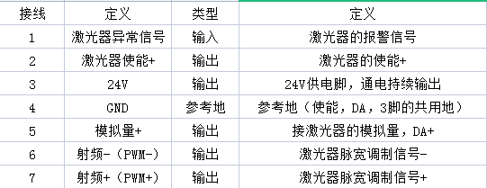
As shown in the figure above, the necessary three groups of signals are
2 / 4 pin enable signal, output 24V voltage control signal during operation
4 / 5 pin analog signal, output rated voltage control signal during operation (10V output at full power, output voltage is the peak power of process divided by (total power of laser in the setting interface divided by 10), assuming that the laser power is 2000 and the peak power of process is 1000, the output voltage is 5V)
Pin 6 / 7 is PWM modulation signal, and the output is 24V during operation
Pin 4 is enabled DA. Common ground of pin 3!!!
II. Wiring matching of laser
Any laser requires the above three groups of signals, but the manufacturer is different and the wiring definition is different. The wiring should be carried out according to the logic of the laser
(individual lasers need trigger signals, such as red light trigger of individual models of Ruike and the trigger of control mode of Ennai laser, which need 24V and should be connected to pin 3 of the control box)
For example: first look at the definition provided in his manual
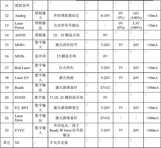
In their definition, enable + is pin 18 and enable - is pin 20 (return end of 18)
be
18 connected to 2
20 to 4
Provide enable signal, and so on. After the wiring is completed, conduct light output test. If the laser does not output light, connect the monitoring of the laser to see which signal does not exist, and then conduct corresponding inspection.
 简体中文
简体中文 English
 العربية
 Français
 Русский
 Español
 Português
 Deutsch
 italiano
 日本語
日本語 한국어
한국어 Nederlands
 Tiếng Việt
 ไทย
ไทย Polski
 Türkçe
 ພາສາລາວ
 ភាសាខ្មែរ
 Bahasa Melayu
 ဗမာစာ
ဗမာစာ Filipino
 Bahasa Indonesia
 magyar
 Română
 Čeština
 Монгол
 қазақ
қазақ Српски
 हिन्दी
 فارسی
فارسی Kiswahili
 Slovenčina
 Slovenščina
 Norsk
Norsk Svenska
 українська
 Ελληνικά
 Suomi
Suomi Հայերեն
 Latine
 Dansk
Dansk Shqip
Shqip বাংলা
বাংলা Hrvatski
 Afrikaans
 Gaeilge
 Eesti keel
 Oʻzbekcha
 latviešu
 Aymara
 Azərbaycan dili
 Беларуская мова