注意:
1.请确保文中的激光器图示与您使用的激光器为同一型号 本文适用 YLR-14 型号
2.如激光器厂家信号更改,则下列接线失效,请按照厂家提供的定义接线
Attention:
1. Please make sure that the laser icon in the article is the same model as the laser you are using
2. If the laser manufacturer's signal changes, the following wiring fails. Please connect the wiring according to the manufacturer's definition
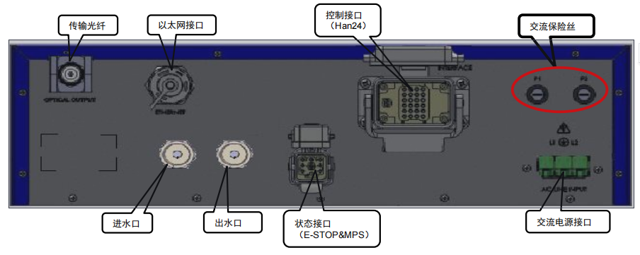
YLR-14 光纤激光器图示①
Figure 1 shows the YLR-14 fiber laser
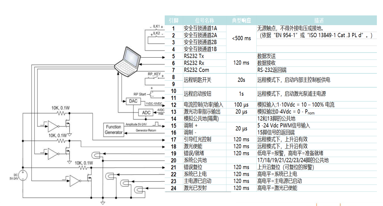
接线逻辑
1.首先短接Han24中的【1/4】【2/3】互锁信号,【8/9】短接
2.其中【10/11】使用带锁按钮①接常开脚,10/11导通
Wiring logic
1. First short-circuit the [1/4] [2/3] interlock signal in Han24, [8/9] short-circuit
2. Where [10/11] use the lock button ① to connect the normal opening pin, 10/11 conduction
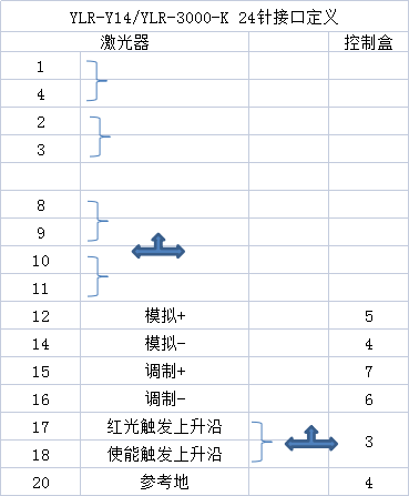
激光器的12/14脚分别接控制盒信号接口三的5/4脚提供模拟量信号
激光器的15/16脚分别接控制盒信号接口三的7/6脚提供PWM调制信号
激光器的17/18脚一起接控制盒信号接口三的3号脚提供使能和红光信号触发,但由于是上升沿触发,所以中间使用带锁的按钮②接常开脚
激光器的20号脚为公用地,接控制盒的4号脚提供参考地
4.开机顺序
激光器上电--按下带锁按钮①--按下带锁按钮②-正常焊接
The 12/14 pins of the laser are respectively connected to the 5/4 pins of the control box signal interface 3 to provide analog signals
The 15/16 pins of the laser are respectively connected to the 7/6 pins of the signal interface of the control box to provide PWM modulated signals
The 17/18 pin of the laser is connected to the No. 3 pin of the signal interface of the control box to provide enable and red signal trigger, but because it is triggered by the rising edge, a lock button (2) is used in the middle to connect the normal opening pin
The No. 20 foot of the laser is the public land, and the No. 4 foot of the control box provides the reference ground
4. Boot sequence
Power on the laser - press the lock button ①- Press the lock button ②- Normal welding
 简体中文
简体中文 English
 العربية
 Français
 Русский
 Español
 Português
 Deutsch
 italiano
 日本語
日本語 한국어
한국어 Nederlands
 Tiếng Việt
 ไทย
ไทย Polski
 Türkçe
 ພາສາລາວ
 ភាសាខ្មែរ
 Bahasa Melayu
 ဗမာစာ
ဗမာစာ Filipino
 Bahasa Indonesia
 magyar
 Română
 Čeština
 Монгол
 қазақ
қазақ Српски
 हिन्दी
 فارسی
فارسی Kiswahili
 Slovenčina
 Slovenščina
 Norsk
Norsk Svenska
 українська
 Ελληνικά
 Suomi
Suomi Հայերեն
 Latine
 Dansk
Dansk Shqip
Shqip বাংলা
বাংলা Hrvatski
 Afrikaans
 Gaeilge
 Eesti keel
 Oʻzbekcha
 latviešu
 Aymara
 Azərbaycan dili
 Беларуская мова